Gentlemen,
I have a barn with 50 amp 240 service. It now basically has lights and 120 outlets. Is it OK to add a 50 amp receptacle for a welder with the
idea that
I won't run the welder at full power?
Thanks in advance for any comments.
RogerB
Gentlemen,
I have a barn with 50 amp 240 service. It now basically has lights and
120
outlets. Is it OK to add a 50 amp receptacle for a welder with the idea that
I won't run the welder at full power?
Thanks in advance for any comments.
RogerB
"Jim Wilkins" wrote in message news:t18aoj$pv4$[email protected]...
I run a Lincoln Square Wave 175 welder at about 120A through a 50A breaker (240V) in a 200A panel (electric heat). The breaker hasn't tripped yet, even when rods stick. 120A has been good for up to 1/2" plate with 1/8" 7018
rods.
---------------------------
At 100% efficiency 120A at 25 arc volts would equal only 12.5A through
the breaker at 240V. The Lincoln has active SCR control and I haven't measured its efficiency because welding projects don't appear to
affect my home electric bill.
"Richard Smith" wrote in message news:[email protected]...
...
My largely home schooling in electrical engineering missed that part. https://www.nrcan.gc.ca/energy/products/categories/commercial/arc-welding/14703
The idling power loss in the 50A buzz box transformer measured 1/4KW
at 120V in and 1/2KW at 130V in. The no-load magnetizing current is proportional to input voltage up to 90VAC, then rises rapidly as the
core goes into saturation. They are made that way to limit the welding current, as when an electrode sticks. I needed to know because a
Powerstat variable autotransformer sets the output voltage and
excessive current will burn out its contact brush.
This is the tool that measures AC current without having to disconnect
the wire.
https://www.amazon.com/Clamp-Meters/b?ie=UTF8&node=5011680011
I have the UT210E because it also measures DC current and reads low
enough to check the power-off drain from a car battery. https://www.autotrader.co.uk/content/advice/why-is-my-car-battery-draining-ways-to-prevent-it?refresh=true
On 3/19/2022 9:18 AM, RogerB wrote:
Gentlemen,
I have a barn with 50 amp 240 service. It now basically has lights
and 120
outlets. Is it OK to add a 50 amp receptacle for a welder with the
idea that
I won't run the welder at full power?
Thanks in advance for any comments.
RogerB
I don't know but I run my 65amp welder on a 50 amp circuit all the time.
I do not recall ever tripping a breaker. Most of the time you WON'T
run your welder at its max setting. Maybe never depending on the work
you do. If the breaker trips you stop welding and reset the breaker. I
do not know how your sub panel is setup, but the welder circuit should
be on its own breaker even if its the same size as the incoming circuit.
Its "probably" ok, but I have not seen the barn. However to give you an idea. Go add up the current limit of all the circuits in a house. Its almost always much more than the main breaker on the service entrance.
My shop has a 100amp sub panel feeding it, and off that sub panel are
two more sub panels. One is 100 amps, and one is 60 amps. The only
time I recall tripping one of the main breakers was when I accidentally shorted a transformer while repairing a machine.
MAKE SURE YOUR WIRING IS UP TO THE TASK. DO NOT SKIMP. FOR "NORMAL"
SHOP WELDING IT SHOULD WORK, AND YOU CAN PROBABLY EVEN LEAVE THE LIGHTS ON.
"Richard Smith" wrote in message news:[email protected]...
Isn't a "rule of thumb"
50% efficiency for copper-and-iron transformer machines
90%+ efficiency for inverter welding machines
?
So start with your calculation
(/
(* 120 25) ;; 3000 ;; W
240.0) ;; 12.5 ;; Amps
then double the Amps assumed at the wall-socket ie. 25A
if is a transformer machine.
That inverters are so efficient is rather obvious from the welds you
can run without ever tripping the breaker.
--------------------
My largely home schooling in electrical engineering missed that part. https://www.nrcan.gc.ca/energy/products/categories/commercial/arc-welding/14703
The idling power loss in the 50A buzz box transformer measured 1/4KW
at 120V in and 1/2KW at 130V in. The no-load magnetizing current is proportional to input voltage up to 90VAC, then rises rapidly as the
core goes into saturation. They are made that way to limit the welding current, as when an electrode sticks. I needed to know because a
Powerstat variable autotransformer sets the output voltage and
excessive current will burn out its contact brush.
This is the tool that measures AC current without having to disconnect
the wire.
https://www.amazon.com/Clamp-Meters/b?ie=UTF8&node=5011680011
I have the UT210E because it also measures DC current and reads low
enough to check the power-off drain from a car battery. https://www.autotrader.co.uk/content/advice/why-is-my-car-battery-draining-ways-to-prevent-it?refresh=true
"David Billington" wrote in message news:t1ijcu$25h$[email protected]...
I bought a UT210E after your recommendation and it was useful but I now
find it doesn't work any more. It turns on and responds to the selection switch and buttons and on resistance or voltage it shows its working
when you connect an item to test and then just displays 0.000 which is
all it does in any mode now. I can't see anything wrong internally and
new batteries had no effect so it looks like its dead or at least of no
use whatsoever.
-------------------
Sorry.
There is a lot of info on line about them, including calibration and
hacking the code. I haven't tried any of it.
"David Billington" wrote in message news:t1io3n$7ca$[email protected]...
On 24/03/2022 21:26, Jim Wilkins wrote:
"David Billington" wrote in message news:t1ijcu$25h$[email protected]...I've just started to look at it but haven't found any useful stuff yet.
I bought a UT210E after your recommendation and it was useful but I now
find it doesn't work any more. It turns on and responds to the selection
switch and buttons and on resistance or voltage it shows its working
when you connect an item to test and then just displays 0.000 which is
all it does in any mode now. I can't see anything wrong internally and
new batteries had no effect so it looks like its dead or at least of no
use whatsoever.
-------------------
Sorry.
There is a lot of info on line about them, including calibration and
hacking the code. I haven't tried any of it.
I wonder as it has firmware if it's trashed its calibration settings,
I've seen that sort of behaviour on a number of occasions where the
device would occasionally write to places it shouldn't do to ill effect.
--------------------
I have several of Uni-T's products. My impression is that they are
bright young guys with lots of good ideas but are a little short of
practical experience on implementing them reliably. Several times I've noticed that new electrical engineers don't always know how real-life components deviate from the theoretical ideal. https://en.wikipedia.org/wiki/Dielectric_absorption https://www.murata.com/~/media/webrenewal/products/emc/emifil/knowhow/12to14.ashx
https://electrical-engineering-portal.com/time-current-curves
I learned when I was in the testing business, measuring those things.
Many of the parts I've bought on line don't quite meet their specs.
That was true of Radio Shack too, but surprisingly some were much
better than specified, like a "50V" rectifier bridge that tested OK to
500V.
I have another brand of Chinese DC voltage/current/power meter that
goes haywire if connected to solar panels, apparently from the
marginal operating voltage at dawn and dusk.
Then again I found a bug in an Intel IC's reset circuit and a Texas Instruments computer's microcode. The latter got me promoted to
Engineering.
Many of the Ph.D theses I've read tend to demonstrate that the author
has the potential to do serious research, but they and their advisors
lack practical experience.
I think I was most useful when I brought my wide but not that deep multi-disciplinary knowledge to a researcher whose education had
concentrated in one field.
...
As brilliant and well educated as he is, John didn't know how to
fabricate and join sheet metal until I showed him press-in PEM nuts.
"Richard Smith" wrote in message news:[email protected]... >>
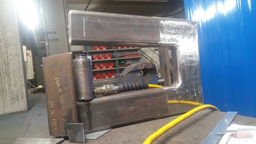
I did this and kept my job
"Tensile-test rig for beam-configuration fillet-weld samples"
Movie of - 10 seconds - shared on "Dropbox"
https://www.dropbox.com/s/ua4ke9y4w3bcp6d/210122_fwtr.mp4?dl=0
Sound is like firing a NATO 7.62 round inside the building.
I think they politely pretended they didn't know because they had a
feeling I could be a useful "card up their sleeve" if the customer was
disputing their weld quality and properties.
--------------------
Wow, dramatic, and your test rig works very well.
Is that sudden brittle fracture typical of welds in tension? I thought
it was better to have a joint plastically deform somewhat and
distribute any localized stresses before fracturing.
"Jim Wilkins" <[email protected]> writes:
"Richard Smith" wrote in message news:[email protected]...
I did this and kept my job
"Tensile-test rig for beam-configuration fillet-weld samples"
Movie of - 10 seconds - shared on "Dropbox"
https://www.dropbox.com/s/ua4ke9y4w3bcp6d/210122_fwtr.mp4?dl=0
Sound is like firing a NATO 7.62 round inside the building.
I think they politely pretended they didn't know because they had a
feeling I could be a useful "card up their sleeve" if the customer was
disputing their weld quality and properties.
--------------------
Wow, dramatic, and your test rig works very well.
Is that sudden brittle fracture typical of welds in tension? I thought
it was better to have a joint plastically deform somewhat and
distribute any localized stresses before fracturing.
It is sudden fracture with no warning.
Reason had to make the rig - sudden elastic energy release at full
load. Unfair to do to a shop press.
But brittle - not really. The fracture surface looks like "microvoid coalescence". The fracture looks to be a shear in line with the
applied stress, so sudden fracture but ductile fracture mode??
I can see where you are going with your question about the overall
joint, but the good solution has a different logic.
You are thinking that virtue is in the joint be able to and actually plastically deforming.
The good solution is totally different.
Given the strength you see is way higher than expected. There is no
sign of the yield stress manifesting - neither the plate steel nor the
weld metal has its yield stress show. This makes no literal sense,
but - the sudden fracture is at stress about the same as the rated "Ultimate Tensile Strength". You see around 560MPa with S355 steel (355MPa
yield) welded with G3Si1 (ER70S-6) GMAW welding wire. Why I can't see
how this makes sense that the strength you see matches the UTS is that
the UTS is obtained in uniaxial tensile test of a long cylindrical
sample and there is plastic necking - with UTS being breaking-force/*original*-area. The break area is much smaller than
the original cross section in relation to which the yield stress
manifests.
*** If anyone can explain this about seeing break stress same as uniaxial-test UTS please offer that explanation ***
Anyway, long digression into mechanistic detail.
Seeing a very high stress at the joint before anything happens, it
follows that you can protect the joint(s) by ensuring that the
sections you are joining would have general yielded at a lower stress
than would break the joints :-)
So for many structures you check that distributed general beam bending
- the tabulated or easy-to-calculate "Euler-Bernoulli" plastic yield
load - is less by a satisfactory margin than the sudden break
strength of the fillet welds.
As I said - I think if you do that you fully protect the joints with
their high strength but sudden breaking behaviour.
*** comment requested on this too - if you know the answer please
share ! ***
..............It is sudden fracture with no warning.
... Yours represents actual service better.
... One piece with slightly smaller dimensions than the rest didn't
change at the deflection calculated for A36 steel and may have been
A50. I had to bow it by over a foot to straighten it. While it was
loaded I didn't get close enough to take measurements.
... One piece with slightly smaller dimensions than the rest didn't
change at the deflection calculated for A36 steel and may have been
A50. I had to bow it by over a foot to straighten it. While it was
loaded I didn't get close enough to take measurements.
| Sysop: | Keyop |
|---|---|
| Location: | Huddersfield, West Yorkshire, UK |
| Users: | 741 |
| Nodes: | 16 (2 / 14) |
| Uptime: | 68:26:13 |
| Calls: | 12,448 |
| Calls today: | 3 |
| Files: | 15,194 |
| Messages: | 6,537,585 |